![]()

![]()

|
The bridge and upper decks at the center of the saucer-shaped Primary Hull top have a profile that appears too flat on the top and should be more rounded. I replaced the entire part with the saucer top from the old Enterprise model. The older pressings of the kit included a saucer top with a more rounded bridge and upper deck section than later releases. Though still not correct, the older part looks better. Parts from the new kit were later used to restore the older model. The only paint to remove on the old part was on the windows, which sanded off easily. The old decals, long ago applied to bare plastic, almost came off by themselves. One feature of the kit that has always been questioned by fans of the show is a series of heavy raised panel or grid lines covering the surface of the Primary Hull Top. When viewing original Star Trek episodes, no lines are visible on the Enterprise. Photos taken at the Smithsonian show no visible grid lines on the top of the saucer but the limited viewing angle made it tough to be really sure. (More about the grid lines later.) Ed Dietrich's Lucifer illustrated how removing the lines from the saucer made the model look a lot less like a toy. I decided the model would look better with the lines removed. As recommended in the article "The Ultimate Starship" in Famous Spaceships of Fact and Fantasy, I shaved off the grid lines with a #17 X-acto chisel blade. Spots where the blade cut too deep were filled with Squadron Green Putty and the part was sanded smooth with 320, 400 and then 600 grit sandpaper.
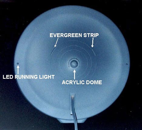
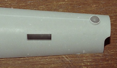
Another odd feature of the kit is a trio of quarter inch wide, cuplike depressions on the saucer bottom. These depressions are roughly an inch and a quarter from the saucer center and appear to be unevenly and asymmetrically spaced. They were filled with putty and sanded flat. The raised concentric circles on the Primary Hull bottom were shaved off. New circles were scribed with a divider at radii of two, one and a half and one inch, and pieces of Evergreen .040" strip styrene were added. The flat, raised platform in the center of the part was sanded until it was completely blended into the contour of the saucer bottom. |
 |
|
| All three light pairs (port running lights, starboard running lights and sensor domes) were wired together in parallel to one common pair of wires. The Primary Hull was then glued together with the common pair of wires running out the opening on the underside. |
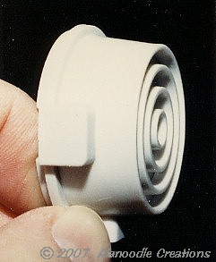
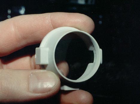
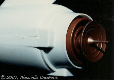
When AMT recut the molds for the kit in the 1970s, the part that really suffered the most in regards to accuracy was the cigar-shaped Secondary Hull, also referred to as the Lower Hull and in Trekkie Lore, the Engineering Hull. Ertl made some changes to the sub-assembly that made it even less accurate than before. The front of the Secondary Hull Front Cover has three concentric inner rings that are flush with the outer front edge of the part. On the big model (and original pressings of the kit), the outermost of the three rings extends forward a little. I cut all three of the rings out and replaced them with a section of 1 1/4 inch acrylic rod turned on a lathe. When assembled into the Front Cover, the sensor platform looks much better. |
 |
 |
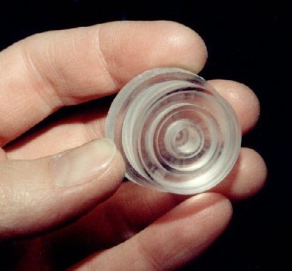 |
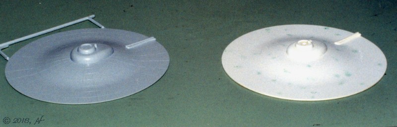
 Dish from the new kit is on the left, the dish from the old kit on the right. |
|
The retooling of the kit left the Main Sensor and Navigational
Deflector
dish with the wrong shape. It was replaced with the dish from the old Enterprise
model which was pretty accurate.
Old paint was removed easily with oven cleaner and a tooth brush. The dish's diameter was turned down on a lathe from 1 3/16 inches to just under an inch. Once assembled, the sensor dish and platform were sprayed with Tamiya Copper before assembling them into the Secondary Hull Front Cover. |
 |
 |
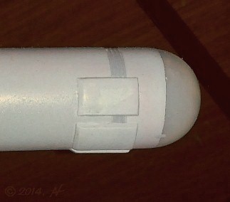
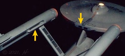
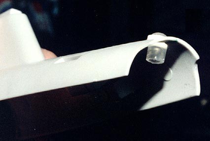
| The 1970s retooling completely eliminated a dome on the top back end of the Secondary Hull (referred to as the Aft Navigational Beacon or the Shuttle Bay Observation Dome in Trekkie Lore). A dome was made from a short section of quarter-inch diameter acrylic rod rounded over with a file and trimmed with a section of plastic tube. It was lit from underneath with a six-volt model railroad lamp. |
 |
 |

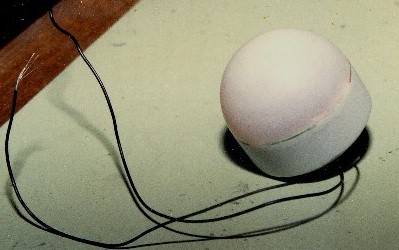
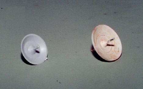
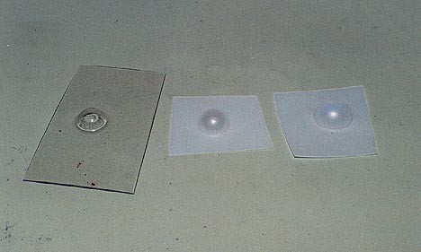
The biggest challenge presented by this build was figuring out how to faithfully depict the warp drive effect in a space less than an inch wide. I considered animating the warp domes using hobby-size electric motors but nothing was ever built. Several options were explored on paper but I decided that the space inside the kit's engine nacelles was just too tight to do what I wanted with the resources that were available. Coming up with a workable design for a static warp effect would be easier but not necessarily easy. The warp domes supplied with the model kit are too thick and opaque, so they would need to be replaced. I played around with different things like Plastruct acrylic domes and the plastic capsules found in gumball machines. After some experimentation, I wound up making my own parts. I had access to a small vacuform machine at the model shop where I worked. I used a three layered system of domes made from .015" thick translucent or "natural" sheet styrene and .030" clear copolyester. Vacuform patterns were made by sinking marbles and a wood ball into wood bases as seen, below left. To make the domes, a piece of sheet plastic would be heated until was softened. The softened plastic would be "pulled" over the pattern. A vacuum pump would then suck out all of the air between the pattern and the plastic, causing the rubbery plastic to conform perfectly to the shape of the pattern underneath. The plastic would be cooled by blowing air on it, causing it to keep the shape of the pattern when removed. |
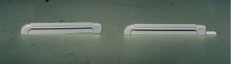
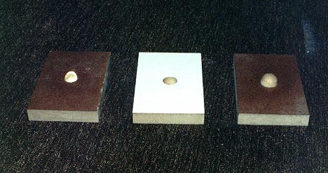 Engine dome vacuform patterns from left to right: inner "color dome", middle diffuser dome, outer dome. |
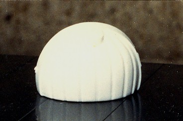
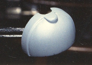
 Vacuformed domes from left to right: "color dome", diffuser, outer dome. |
The
kit's two "propulsion unit domes" were removed from their molded
collars
with a razor saw, leaving the forward bevel. The new, scratch-built
dome
assemblies were then glued to the flat back ends of the dome collars.
This
was because the vacuformed outer domes were a touch oversize. The domes
fit on the back end perfectly while the beveled forward end of the
collar
blended perfectly with the ribbed front ends of the engine nacelles.
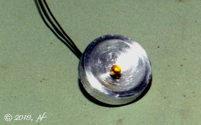
The translucent domes would remain un-painted and would make up the two front layers. The clear color dome would be painted with Tamiya Clear Red (X-27) in a random vane pattern and placed behind the two frosted domes. An amber three-volt model train lamp was placed into a milled aluminum reflector. The reflector would also act as a heat sink to prevent the bulbs from getting too warm in such a tight enclosure.
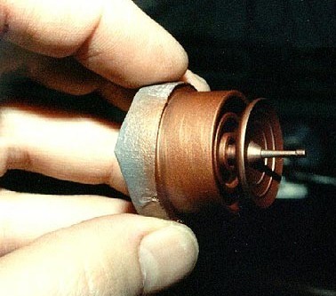
Above is a drawing of the warp dome lighting assembly showing an
exploded
view of components. Below, left is
an amber bulb in one of the aluminum reflector/heat sinks. Below, right
is a completed dome assembly.
|
When gluing the warp engine halves together, if the molded locating pins were used, the warp support pylons were offset by about 1/32 of an inch, front-to-back. I cut off the pins and lined up the engine halves at the pylons. I sanded the front and back ends of the engines to fix an offset in the length. Grooved detail at the front of the nacelle was a close enough match to easily blend in with putty and a file. The grooves at the back were offset by about a sixteenth of an inch. They were filled with putty and sanded smooth. The rectangular grids on the insides of the engine pylons possess some nasty ejector pin marks. They were shaved and sanded off and would be replaced by decals after painting.
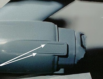
Each of the "propulsion unit shields" was cut into three sections each
about 5/16" wide. The front and rear of each section was beveled and
they
were placed in position underneath the engine domes, 1/4" behind and
about
1/16" apart. Tabs were added to the "intercoolers" made from 1/4"
sections
of .040" x 1/16" strip styrene.
After the grooves in the "shuttle craft hangar deck" were filled in, assembly of the model was completed as per the kit's instructions. All the sub-assembly circuitry was routed to the secondary hull and connected to a 1/8" phone jack which was placed at the bottom of the secondary hull, close to the model's center of gravity. This power jack would double as the model's mounting point. The secondary hull was reinforced by lining the inside with A&B "plumber's" putty which is very hard and durable after it's cured. Quarter-inch ribs of the putty allow the phone jack to support the top-heavy model's weight without putting much stress on the thin plastic or the glued joints. |
 |
 |
|
 |
 A powered display stand was made from a 1 1/2" thick piece of basswood milled out to accommodate four "C" batteries, a switch and an external power source jack. A 1/8" phone plug was epoxied to a well supported 5 1/2" long section of Plastruct 5/16" ABS tube. The phone plug provides six volts and a very secure mounting point for the model. An external power source can be plugged into the jack in the base which also cuts off power from the batteries. |
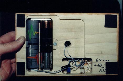 Bottom of stand showing batteries and wiring. |
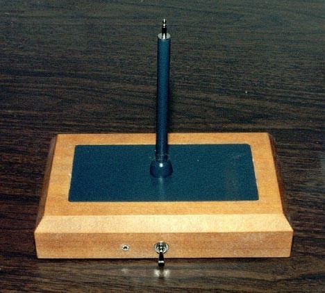 Back of powered display stand. Note the external source jack and on/off switch. Plug on top of rod plugs tightly into bottom of model. |

|
|
|
|
|
|
|
|
|
|
|
|
![]()

![]()
![]()


![]()
![]()