

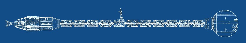
Drawing modified from
Shane
Johnson's U.S.S. Discovery Blueprints
Drawing modified from
Shane
Johnson's U.S.S. Discovery Blueprints
| Scale Modeling Tutorial by
Alan Nadel This tutorial originally appeared on the 2OO1: A Space Odyssey Collectibles Exhibit website |
|
|
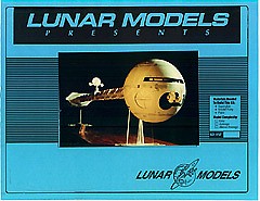
| The kit
came in a
heavy corrugated cardboard box with a label and photograph of a
finished,
painted kit. Larger parts were in their own separate bags, smaller
parts
separated into two smaller bags. The fuel pods which came in three
sizes
were bagged separately. The 3 long spine parts were wedged into the box
diagonally, un-bagged.The kit's instructions can be viewed as a PDF
file
by clicking here.
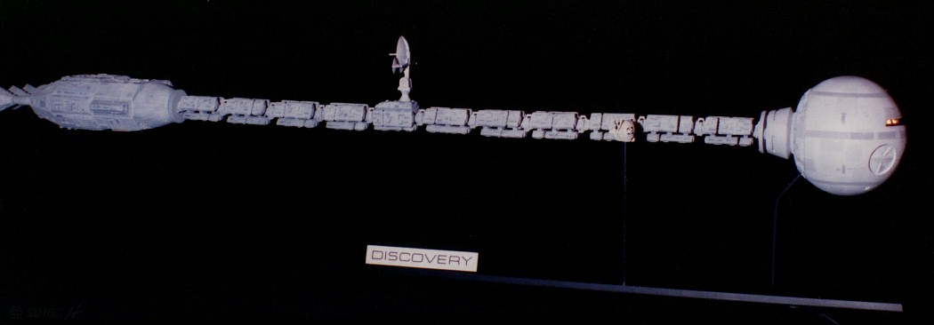
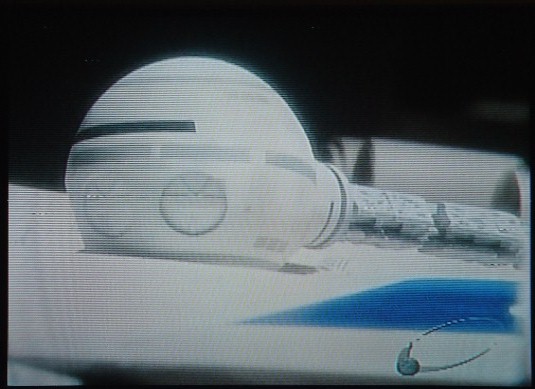
The kit is patterned after the Discovery as it appeared in the 1984 movie 2010: The Year We Make Contact and is slightly different from the Discovery in 2001. Some modifications to the kit would be needed to make this model look more like the Discvovery from the 1968 film. Research was not easy to come by in the early 1990s. There was no Internet like we have today. The best resource I had was a VHS print of the film which I could view with a 19-inch TV set. Even with freeze-frame, the image quality of what we now call "standard definition" TV was just not up to the task of providing an image sharp enough for close-up detail. |
 |
|
|
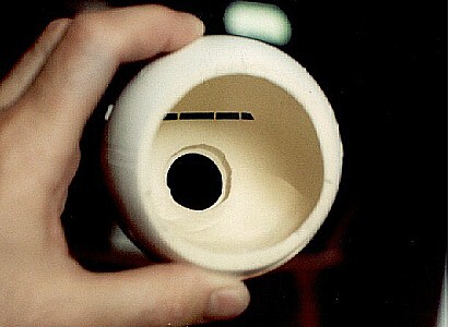
Fortunately,
the kit came with an extra bay door to build the kit with the pod-bay
open.
I used it to replace the removed door. A hold-down jig was made to hold
the
sphere on a milling table to make a flat seat for the new door. The 3/8
inch thick resin of the part was cut with an end mill to just under 1/8
inch and the
new door was glued into place.
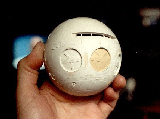
Overall, detail looked klunky and a little exaggerated with many air bubbles in the resin. Some panel lines were at slight angles and others almost looked as if they were scribed freehand. Most of the detail was filled with putty and sanded smooth until the part was nearly featureless. Instead of scratch-building the lost detail back onto the sphere, I decided it would be added back to the model as painted-on features. |
 |
 |
|
 |
|
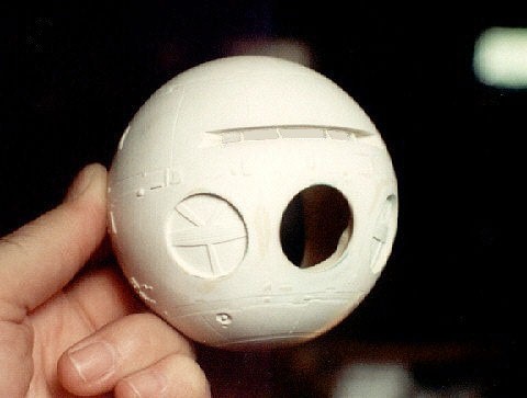
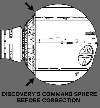
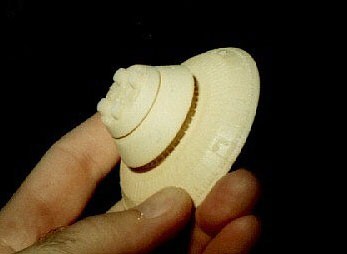
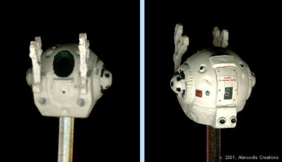
As cast,
the Command Section has eight evenly-spaced depressions which are
labeled
in the blueprints as "reaction control thrusters." The Discovery
in the film had only one of these depressions on the forward right
side,
just below the pod-pay door. I filled in the other seven with Squadron
brand filler putty. The air-lock door on the left side of the pressure
sphere was way too deep and looked more like a trench than a door. It
was
also filled with putty. When the putty was cured it was wet sanded
until
flush with the curve of the sphere. Cured Squadron putty expands when
it
gets wet and shrinks when it dries. The putty on the air-lock door
shrunk
just enough to give it a better, more subtle recess.
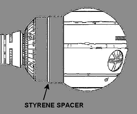
Probably the most obvious problem with the Command Section was that the part was short by 1/8 inch which caused a mismatch between the sphere and the flange behind it. A spacer made from 1/8 inch thick sheet styrene was glued to the back of the sphere which corrected this problem. |
 |
 |
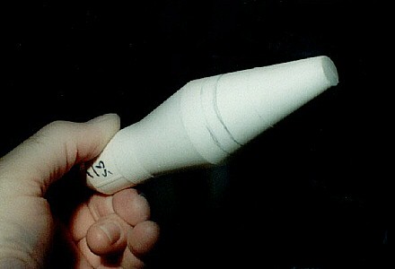
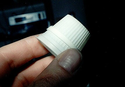
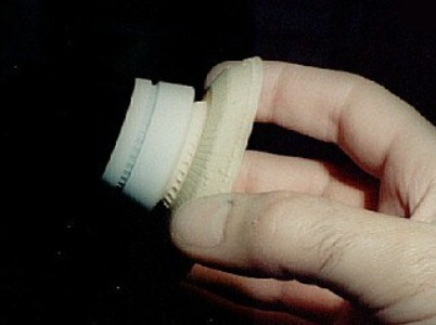
| The conical section behind the Command Section was replaced with a section of a styrene Estes Rocket nose cone detailed with a one-half ounce half-and-half container like the kind served in restaurants. This improved on the accuracy of the part. The part was then drilled out and a piece of 1/8-inch K&S brass tubing was glued inside to reinforce the joint between the flange and the spine. |
 |
 |
 |
 |
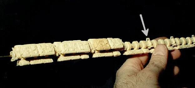
| The three section, 20-inch long spine is made of resin cleverly cast over brass for strength. The two ends are cast over brass rod and the center section over brass tube, making for a secure fit as well as providing locator pins for the Command Section in the front and "Reactor Section" in the rear. The spine of my kit was fairly straight and cast pretty well but I have heard that owners of later kits weren't so lucky. |
|
 |
|
Lunar's instruction
sheet has a diagram showing the locations of the 62 "fuel pods" which
come
in three sizes and are positioned along the spine. Though confusing at
first glance, the instructions were helpful in arranging the fuel pods
in their accurate configuration. In order to ensure that all the pods
wouldn't
look uneven when glued to the spine, a jig was made to hold each one
down
on a milling table and they were all milled to the same thickness. To
glue the fuel pods to the spine, I made another jig to hold them in a
straight line, similar to the milling jig but 24 inches long to hold an
entire row of pods.
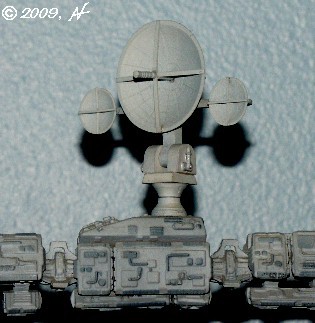
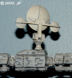
The entire communication antenna and mounting were unusable. The base was inaccurate, being modeled after the Discovery in 2O1O and the antenna mast was not only warped but short cast. The three dishes were anything but dish-shaped and the main antenna's probe was so covered with flash and resin lumps that it took me a while to figure out what it was supposed to be. |
 |
|
 |
 |
|
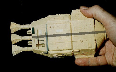
| One of the three engines looked as if it were cast during another run of the kit. While two of them were cast in light tan resin with very sharp detailing. The third was a slightly darker (maybe older?) resin with very soft details and some serious casting issues. It was cleaned up with a Dremel grinding tool and the addition of sheet styrene. |
|
 |
|
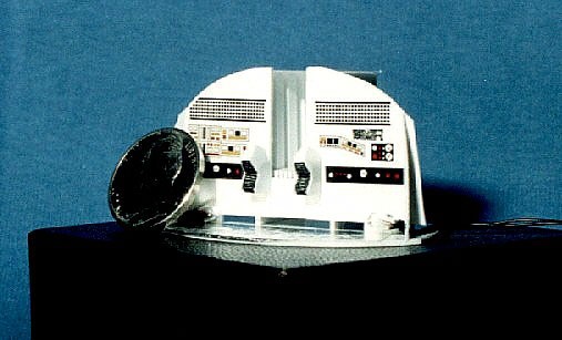
The model
was painted with Tamiya acrylics. Using my trusty Badger 150 airbrush
and
lots of masking material, I painted a series of panels in various
shades
of light grey on the Command Section. Details that were sanded off in
the
process of cleaning up a less than perfect casting job were painted
back
on.
The spine and reactor/engine sections were spray painted with medium gray automotive primer. Details were then colored with a black Sharpie marker. An airbrushed coat of white acrylic paint makes the Sharpie markings just barely visible. The 31-inch long Discovery was mounted on a scratch-built display stand. The stand's forward support post is topped by a 1/8 inch phone plug which connects to a phone jack below and behind the Command Section and provides the 9 volts necessary to light the Command room. The EVA pod is mounted on a 1/8 inch piece of acrylic rod.
Though I didn't keep a record of my work on this model, I'm sure that with all the part cleanup and additional scratch-building the Discovery took at least 40 hours to complete. Though this kit presented many challenges, it was a lot of fun to build. In 2002, the model was filmed for a television program on the Discovery Science Channel called The Great Books - 2OO1: A Space Odyssey which examines the writing of the novel and 1969 film by Arthur C. Clarke and Stanley Kubrick. In a few scenes, actors portray Clarke and Kubrick working at a table covered with typewritten ideas and models from the movie. Discovery is visible stretched across the middle of the table and the command sphere actually appears in close-up. The show is available on YouTube and can be seen by clicking on the image below. The model first appears at about 18 minutes into the show.
|
Go
to the DISCOVERY
Gallery
Page

![]()